|
|
| |
|
|
| |
Sola Sound ToneBender 3-Knob
The Sola Sound 3-Knob ToneBender is another famous installment in the ToneBender line of pedals. This time, the end result
was a circuit that produced an overall softer fuzz, especially when compared to the very aggressive Sola Sound MKII Professional!
This circuit also has a feature that none of the earlier ToneBender had...a tone control! The tone control is something that
I think really sets the 3-Knob apart since you now had the ability to tweak the frequency response of the pedal without having to
resort to input and ouput capacitor changes. If you take a look at the schematic of the Sola Sound 3-Knob ToneBender below, you'll
notice that Q1 and Q2 are arranged in a darlington pair. These two transistors don't even need to be Germanium since Q3 is the one that
actually does the fuzzing. You could use a pair of lower gain PNP Silicon transistors, like the 2N3906 with good results. Just remember
that Q3 does need to be Germanium in order to sound right...and the diode across the base-emitter of Q3 also needs to be
Germanium for it to function properly. Does that diode look familiar, by the way? If I recall correctly, that diode is there, reverse biased,
to impart temperature stability to Q3 so that it doesn't start doing strange things if/when the temperature begins to climb. Also take a
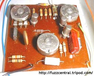
look at the 220K resistor between the "tone" and "volume" pots. That resistor can be removed and replaced with a wire lead, which will give you more output volume. Below
is a picture of the circuit board in a Sola Sound 3-Knob ToneBender:
Below is a schematic of the original Sola Sound ToneBender 3-Knob:

The Park Fuzz Sound is another version of the Sola Sound ToneBender 3-Knob, except in this circuit the "fuzz" pot has been eliminated and replaced
with a 25µF capacitor. This arrangement will keep the fuzz all the way up all the time, which could be a good thing and could be a bad thing...
depending on how you like to play. Once again, you get a tone control. Also notice that there are some other minor component value changes
in the 2-Knob Park Fuzz Sound, highlighted in red in the schematic below. Below is the schematic of the 2-knob Park Fuzz:
And here's yet another version of the Park Fuzz Sound...the 3-Knob fuzz. As you can see, the circuit has the same "anatomy" as the Sola Sound
3-Knob, but with some minor component value changes, which are highlighted in red. The "fuzz" control has returned in this version so that you
can adjust the intensity of the fuzz, unlike the Park Fuzz Sound 2-Knob, which is always going full-tilt. Below is the schematic of the 3-knob
Park Fuzz (thanks to Stuart Castledine for the schematic):
While we're talking about all these variations on the Sola Sound 3-Knob ToneBender, we can't possibly forget one of Sola Sound's biggest partners
in fuzz...Vox! Yes, even Vox had a version of the 3-Knob which they called the ToneBender MKIII! As you can see from the schematic below, it's almost
the same as the Park Fuzz Sound 3-Knob above. The only difference is that the 2200pF capacitor in the tone control section was changed to 2000pF.
Below is the schematic of the Vox ToneBender MKIII (thanks to Stuart Castledine for the schematic):
The Prescription Electronics Yard Box is a more recent take on the Sola Sound ToneBender 3-Knob. The circuit remains largely the same with only
a couple of component value changes, which are highlighted in red on the schematic of the circuit below. Notice that the fixed resistor between
the "tone" pot and "volume" pots has been replaced with a 250K "gain" pot, which basically acts as a second volume control. I'm not sure how
useful this modification is...a lot of people like the circuit is better without anything (variable resistor or fixed resistor) between the tone
pot and volume pot...this will give more output volume. Below is the schematic of the Prescription Electronics Yard Box:
|
ToneBender 3-Knob PCB
|
Here
|
ToneBender 3-Knob Layout
|
Here
|
ToneBender 3-Knob Parts List
|
Here
|
Build Difficulty: Moderate
|

|
|
The PCB and Layout files that I have linked above are on Stuart Castledine's "Guitars, Amps and Effects" website.
You can use his PCB and Layout files to build several different versions of the ToneBender 3-Knob. I've been a regular visitor to
his website since I started building effects pedals years ago and it has been an invaluable resource for information on ToneBenders
and many other effects pedals from the 1960s and 1970s. Stuart also assisted greatly with many of the effects projects presented on
this site, including the ToneBender MKII Professional, Vox ToneBender and Vox Clyde McCoy wah.
|
|
|
| |
|
|
|
