|
|
| |
|
|
| |
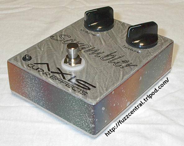
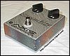
Ampeg Scrambler
This is the clone of the very rare Ampeg Scrambler, which was built in very small numbers back in
the late 60s. Originals are very rare these days and sell of outrageously high prices when one does become available,
similar to the Tycobrahe Octavia. Guess what? I love this thing! This pedal is everything that I expected it to be
and more! It does a great raspy fuzz like the fOXX Tone Machine, but it can be gradually blended in with the clean
guitar signal.
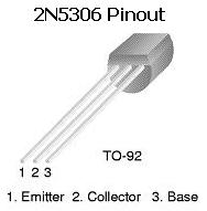
On this one I used the original type 2N5306 NPN darlington transistors just like the original used. Watch out for
these though because the pinout is different! (See the illustration below for the correct pinout.) I also used the
original type diodes, the 1N456. I installed all 5 of them, but I've heard that you can leave some of them out
without any sonic impact. The switch is a 3PDT switch that I got from Steve Daniels, and I also used little socket
to hook the wires up to the LED for a much cleaner appearance, not to mention being easier to install.
I highly recommend this pedal...you won't be sorry if you like a lot of octave! Below is the schematic of the Ampeg
Scrambler:
|
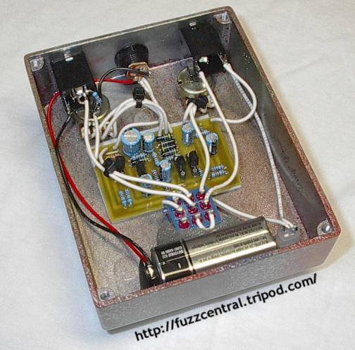
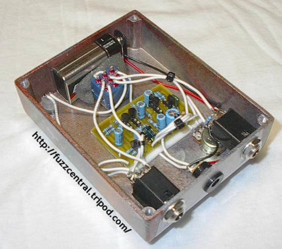
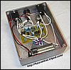
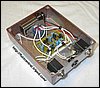
Below are some pictures of my Ampeg Scrambler clone. Click for the full-size image. Use your browser's
"Back" button to return to this page.
|
|
|
|
Here's the pinout of the 2N5306 Darlington transistor. The BC169B also has this pinout, but those
are hard to find these days. In my Scrambler clones I've used the 2N5089 in place of the BC169B with great success.
I've used the 2N5306 because they sound great in the circuit and they're still easy to get from Mouser and several
other parts suppliers.
|
Ampeg Scrambler PCB and Layout
|
TonePad
|
Ampeg Scrambler Parts List
|
Here
|
Build Difficulty: Moderate
|

|
|
The PCB and Layout for the Scrambler posted at Tonepad contains an error that was present in the factory schematic of
the Ampeg Scrambler. The 1µF capacitor on the emitter of Q1 is backwards, which will cause the polarized electrolytic
capacitor to leak like crazy and dump a LOT of voltage onto the bypass switch, causing a very loud pop when the effect
is switched on and off. The correct way to install this capacitor, marked C3 on the Tonepad schematic and layout, is
with the (+) lead facing toward the emitter of Q1...NOT facing the "Blend" pot. If you've been experiencing a loud pop
when using this layout, this is probably the problem.
|
|
|
| |
|
|
|