|
|
| |
|
|
| |
Axis Face Silicon
Revision 3 -- 1/25/2005
Welcome to Revision 3 of the Axis Face Silicon circuit! This
time we're adding even more modifications so that it has all the warmth of a Germanium Fuzz Face-style circuit, but you don't have to
worry about tracking down hard-to-find Germanium transistors that have the right gains and leakages and paying through the nose for them.
The Silicon transistors used in Axis Face Silicon Rev. 3 are easy to get from Mouser Electronics, and they're also cheap to boot! Silicon
transistor don't suffer from temperature instability problems like Germanium transistors and they're not quite as heat sensitive so you can
solder them directly to the circuit board (but still use a heatsink if you choose to do so!). Two of the modifications to the circuit were
submitted to me by Brett Robinson.
Thanks to Brett for his work and for sending these great mods to me!
First off, we're going to make it true bypass
using one of the excellent 3PDT switches, which are the some of the hottest items in the DIY effects hobby at the moment.
True bypass allows you to completely bypass the circuit when it's not in use so that it doesn't have any negative impact on
your tone. The original Arbiter Fuzz Face pedals also had true bypass, but were wired with the "grounded input" style of wiring,
which is somewhat more difficult than the type of wiring that I use (see the FAQ page to see how I wire up a true bypass pedal).
Adding true bypass without the "grounded input" wiring presents us with a new problem isn't an issue with that type of true bypass wiring.
When the effect is switched on and off there can be a pretty significant POP! This is caused by voltage leaking from the input capacitor
and finding its way onto the bypass switch, and when you step on that switch, the voltage suddenly gets shifted to the other pole of the
switch, which produces that loud pop. A quick and easy way to solve this problem is to add a pulldown resistor to the input of the circuit,
between the switch and input capacitor, and then hook the other end of the capacitor to ground. This resistor shunts that leakage
voltage to ground, completely solving the popping. I would use either a 1M or 2M2 resistor for the pulldown. We don't need to add a pulldown
resistor to the output of the circuit because the volume pot is taking care of business there.
For Q1 I followed Jack Orman's "YAFF" lead and used a PN2369A NPN Silicon transistor. The gain of this transistor
ranges from 40 up to 120...sounds a lot like the good ol' Germanium transistors, huh? This transistor will work great in the Q1 position.
For Q2 I'm using the BD139 NPN Silicon transistor, as suggested by Brett Robinson. The gains of these are usually around 130, which will
work perfectly for Q2. These low-gain transistors will help to keep the fuzz from being too harsh, which is a common problem with Fuzz Face-type
circuits that use modern high-gain transistors like the MPSA18. Another added bonus is that Silicon transistors don't suffer form temperature
stability problems like Germanium transistors. The Axis Face Silicon will sound the same no matter what the outside temperature is. To ensure that
the circuit biases properly, I've replaced the 8K2 fixed resistor on the collector of Q2 with a 10K trimpot. This will allow you to dial in exactly
4.5V-5V so that the circuit will sound as smooth as possible.
I've never really liked the way that the 500KA "Volume" pot in the original Arbiter Fuzz Face sounds. To me it
makes the circuit sound very muddy by not letting enough highs out. In order to fix this problem I've chosen a 100KA for the "Level"
control in the Axis Face Silicon. This pot lets just enough high frequencies out. I've heard that Eric Johnson prefers this value in
his Fuzz Faces also. Another common problem with the Fuzz Face is that there just isn't enough output level. In order to get the pedal
good and loud, you would normally have to crank the "Volume" pot up to about 2 o'clock or so. To fix this, I've replaced the 330-ohm resistor
that's in the Silicon Fuzz Face with a 1K2 resistor. This gives the pedal quite a bit of volume boost so that it's good and loud by
11 o'clock in the rotation of the "Level" pot.
One thing that I especially didn't like about the original Fuzz Face circuit was the "bass overload" that the
circuit seems to suffer from. The bass in the circuit is very "woofy" and "farty" sounding...definitely not as tight as I usually
go for. In order to get rid of the woofiness in the circuit, we'll lower the input capacitor value to 0.22µF as suggested by Brett
Robinson. If you think that this value is too small for your tastes and removed too much bass, then you can increase the value to 0.47µF,
0.68µF or 1µF until you find a value that you like the best. Next up we'll be adding a 0.047uF capacitor in parallel with the 1K2 resistor,
which will roll off some of the highs helping to give the circuit a warmer sound, much like a circuit with Germanium transistors. Some will
say that this circuit sounds even better than a Germanium version! Once again, if you think that the addition of this capacitor rolls off
too much of the high end, try out a smaller value, like 0.033µF, which will roll off less highs. This mod was also suggested by Brett. Now,
in order to remove any extra "jagged" highs, and to help prevent RF interference, we'll place a 100pF Silver Mica capacitor across the collector-
base of Q2. This further increases the smoothness and warmth of the circuit. The final capacitor change will be to replace the 22µF capacitor
on the wiper of the "Attack" pot with a 15µF capacitor. This is a feature from the Vox ToneBender that will further reduce bass a tiny bit and
will back off the fuzziness a slightly.
Two things that I think should be addressed in every pedal, whether it's going to have a DC power
adapter jack or not, is power supply filtering and reverse polarity protection. The power supply filtering capacitor, in this
case a 100µF, will help to remove any hiss that may be introduced and will also provide a stable current source for the pedal
since the capacitor will store a charge. The next thing to take care of is reverse polarity protection. In the Axis Face we're
going to put a 1N400X (1N4001, 1N4002, etc.) in parallel with the +9V source and reverse biased. If the battery should ever
be accidentally touched to the battery clip backwards, the diode will short the negative voltage off to ground to prevent it from
possibly damaging the transistors. Better safe than sorry! ;)
The next thing that we're going to do with the circuit is to add a 100K linear taper potentiometer to the input of the circuit, between the
new pulldown resistor and the input capacitor, to act as a sort of a pregain. This mod was originally put on the Fuzz Face-style circuits by
Mike Fuller and the '69 fuzz pedal. We're only going to use the first lug and the wiper lug of the pot since
it only needs to act as a variable resistor. This pot will allow you to reduce the "fizziness" of the fuzz, and will
also allow you to greatly smooth out the texture of the fuzz. The pot should be wired like this: Lug 1 attached
to the input, Lug 2 (the wiper) attached to the base of Q1, and Lug 3 left unconnected. With this wiring the pot will be at
minimum resistance when it's turned fully counter-clockwise, and at maximum resistance when fully clockwise.
Below is a schematic of the Axis Face Silicon Rev. 3, complete with all modifications and additions described above:
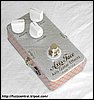
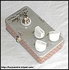
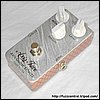
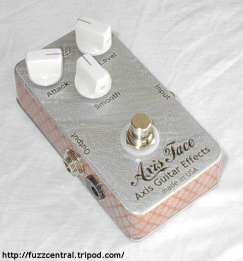
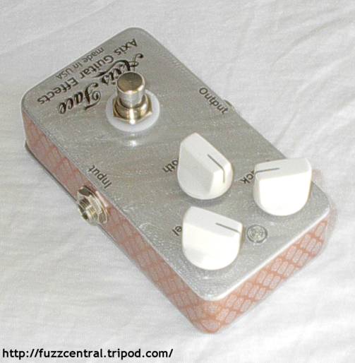
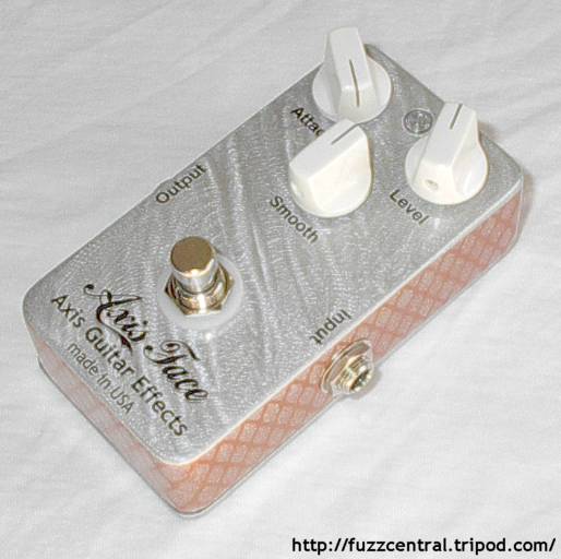
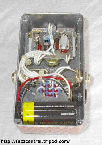
Here are some pictures of the Silicon Axis Face Rev. 3. Click the thumbnails for the full-sized image! Use your browser's "Back" button to
return to this page.
|
|
|
|
|
Note: These files are NOT to be used in a pedal that you are building for profit. The PCB file is
copyrighted artwork and is subject to a licensing fee.
Axis Face Silicon Rev. 3 PCB
|
Here
|
Axis Face Silicon Rev. 3 Layout
|
Here
|
Axis Face Silicon Rev. 3 Parts List
|
Here
|
Build Difficulty: Moderate
|

|
|
The transistor pads in the Axis Face Silicon Rev. 3 PCB will fit a wide variety of different transistors that
have different pinouts. You can use the standard C-B-E pinout and also the B-C-E pinout (like the BD139).
|
|
|
| |
|
|
|
