|
|
| |
|
|
| |
Sola Sound ToneBender Professional MKII
This is probably one of the most legendary fuzz pedals that has ever
existed, and for good reason too! This thing can produce some completely saturated fuzz that is capable of slipping into
feedback easily if you crank it up loud enough. I just can't say enough about this pedal. This is, without a doubt, my
all-time favorite fuzzer. It's a genuine kick in the teeth that will have a permanent spot in my setup. Supposedely,
this is the fuzz pedal that Jimmy Page used on the first couple of Led Zeppelin albums, which makes it even more famous.
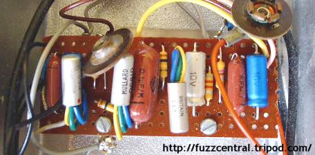
Below is a picture of the circuit board in a ToneBender MKII. Note the silver Mullard OC81D transistors:
Below is a schematic of the original Sola Sound ToneBender Professional MKII:
There are a lot of schematics on the internet that don't have the 0.01µF capacitor on the input jack side
of the input capacitor, but in the original ToneBender MKIIs, there was one there. This capacitor helps to get rid of some
of the intense treble that this circuit has without it. I would recommend that you replace the 8K2 resistor on the collector
of Q3 with a 20K trimpot which will allow you to adjust Q3s collector voltage to -4.5VDC. I would also add a pulldown resistor
to the input of the circuit and a reverse polarity protection diode to help protect those expensive Germanium transistors.
Another nice tweak is to replace the 470-ohm resistor in the original circuit with a 1K or 1K2, which will boost the available
output quite a bit. The original OC81D transistors will be very hard to find...and very expensive if you do find them. In all
reality, they aren't any better sounding than other types, such as OC44, OC75, 2N404, 2N508, 2N527, etc. The transistor gains
for the MKII should be something like 70 for Q1 and Q2 and 100 for Q3. The gains don't have to be exact, but it helps
for them to be close to these values. ***These tweaks are included on the ToneBender MKII Professional PCB and Layout at the
bottom of the page, but they are optional.***
The Marshall Supa Fuzz is an "almost twin" of the ToneBender MKII. The only differences between the two: the input capacitor is
10µF instead of 5µF, the bypass capacitor on the "attack" pot is 10µF instead of 5µF, Q2's collector resistor is 47K instead of 100K,
the resistor from the base of Q1 to ground is 10K instead of 100K, and the transistors are OC75 instead of OC81D. The sound of the pedals should
be nearly the same, although the Supa Fuzz will probably be bassier since the input capacitor is quite a bit larger, especially
with that 0.01µF from input to ground still in place, which removes even more treble. Below is the schematic of the Marshall Supa Fuzz:
Like always, when we're talking about ToneBenders, we can't forget to mention Vox. Vox also made a version of the ToneBender MKII
Professional which they also called the MKII. It was the same basic circuit with only a few minor component value differences. Check
out the schematic of the Vox MKII below, which was emailed to me by Peter, who traced the schematic from an original he owned.
As part of a recent trend of "retro" effects pedals becoming very popular again, Sola Sound reissued the ToneBender MKII Professional...
sort of. The pedal wasn't equipped with the original three-transistor MKII circuit, but rather a modified version of the Fuzz Face.
If you take a look at the schematic of the MKII reissue pedal below, you'll see that there have been a couple of changes and add-ons to
the Fuzz Face circuit. The two most notable additions are the 220pF and 10pF capacitors that are across the collector-base of Q1 and Q2
respectively. These two added capacitors help to smooth out the sound of the pedal, as well as to remove some high-end from the circuit.
The input capacitor has been increased from 2.2µF to 4.7µF, and the output capacitor has also been increased...from 0.01µF to 0.1µF.
These two changes will certainly increase the bass response of the circuit...but it may be too bassy for some players, depending upon their
setup. The "level" pot has been changed from 500KA to 100KA to help remove some of the muddiness from the circuit.
|
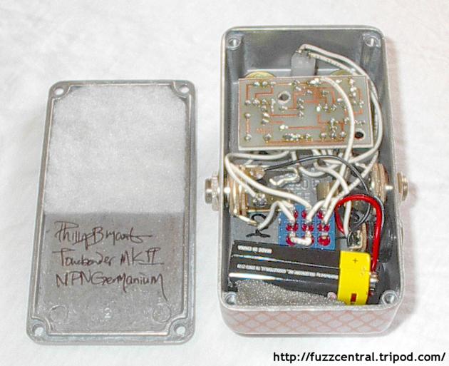
Here is the schematic of my modified version of the ToneBender MKII Professional, the MindBender.
I decided to use NPN Germanium transistors for mine so that I'll be able to use a negative ground arrangement, which allows
use of modern power supplies. You can use 2N388A, SK3861, AC127, and a few other part numbers. I made a few more changes
to the circuit to enhance it's overall performance:
|
- First off, I added a 1M pulldown resistor to the input of the circuit, which will prevent "pops" when using true bypass switching.
- The second change that I made was to replace the 100K resistor on the collector of Q2 with a 47K resistor. This helps
tighten up the sound a bit, making it less "farty", and it helps to increase sustain.
- Third, I changed the 470-ohm resistor that's in series with the output capacitor with a 1K2 resistor. This helps to boost the output
of the pedal so that I don't have to crank up the volume control so much.
- Fourth, I changed the 1KB "attack" pot to 2KB. This change doesn't really have any effect on the tone of the pedal, but it does help
to prevent Q3 from becoming saturated.
- The Fifth change was to replace the 8K2 resistor on the emitter of Q3 with a 20K trimpot so that the collector voltage of Q3 can be
adjusted to exactly 4.5V-5V.
- The sixth and final change that I made to the circuit is the addition of a 1N4001 reverse polarity protection diode. This isn't necessary
but it helps to protect the circuit components in case the power supply is accidentally reversed or if the battery is
touched to the battery snap backwards.
|
Below is a schematic of the MindBender, including test voltages:
|
|
MindBender NPN Test Voltages
|
Vin
|
9.65V
|
Q1 Vc (hfe=70)
|
8.11V
|
Q2 Vc (hfe=70)
|
1.10V
|
Q3 Vc (hfe=100)
|
4.5V
|
|
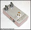
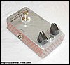
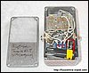
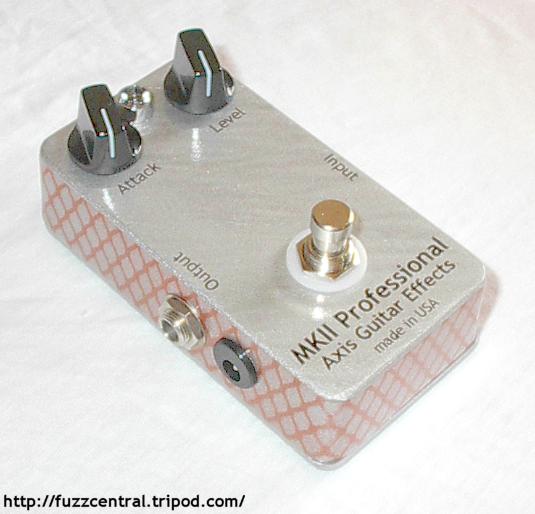
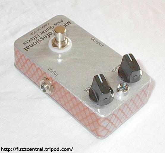
Here are some pictures of the MindBender. Click the thumbnails for the full-size image (pictures updated
November 3, 2004). Use your browser's "Back" button to return to this page.
|
|
|
|
Note: These files are NOT to be used in a pedal that you are building for profit. The PCB file is
copyrighted artwork and is subject to a licensing fee.
ToneBender MKII Professional PCB
|
Here
|
ToneBender MKII Professional Layout
|
Here
|
ToneBender MKII Professional Parts List
|
Here
|
Marshall Supa Fuzz Parts List
|
Here
|
Build Difficulty: Moderate
|

|
MindBender NPN PCB
|
Here
|
MindBender NPN Layout
|
Here
|
MindBender NPN Parts List
|
Here
|
Build Difficulty: Moderate
|
|
|
|
|
| |
|
|
|
