|
|
| |
|
|
| |
Vox Clyde McCoy Wah
The Vox Clyde McCoy wah pedal is probably one of the most legendary wah pedals that was ever
manufactured. It was used by a large number of famous musicians, including Jimi Hendrix. There has been a lot of
discussion over the years about what makes a McCoy sound like a McCoy, and after asking this question several times
myself, I decided to get to the bottom of the matter once and for all. Although some of the material that is presented
here may be controversial to some, I assure you that none of it is made up...everything was observed on original
unmodified Vox Clyde McCoy circuit boards. Of course, with pedals manufactured during the 1960s and most of the
1970s, it's really hard to say that a every single one of any pedal always came with a certain part value. Parts
substitutions were quite common...if they didn't have one part value on hand, they would take the closest thing that
had and solder it in...
"Cross your fingers boys, let's hope it works!"
From the research that I've done and the emails that I've sent and receieved, I've generated a list of unique things
that appeared in the McCoy and probably in other 1960s wah pedals. This list might not be complete because like I
said earlier, parts substitutions were common and so were slightly different circuits.
|
- At the input of modern wah pedal circuits the 68K input resistor comes before the input capacitor. In the McCoy
circuit the 68K input resistor comes after the 0.01µF input capacitor. This doesn't really make any difference in the sound
of the circuit, but is unique to the older wah pedals.
- Some of the Clyde McCoy wahs had a 100K resistor paralleling the inductor while others had the standard value of
33K. Why were there different values on circuits that were supposed to be the same? Who knows...
- The inductor on the circuits that I've seen are Halos, both "large hole" and "small hole" versions. The closer the
inductor is to 500mH, the better! There have been reports of inductors other than Halos being used, but it appears that the
Halo was by far the most common.
- The electrolytic capacitor in the circuit is a Ducati 4µF non-polarized instead of the standard 4.7µF polarized capacitors
found in other wah circuits.
- The transistors that were used in 1960s wah circuits were low to medium gain compared to the very high gain MPSA18 transistors
that are used in modern wah pedals. The lower gain transistors contribute to more bass in the circuit. The McCoy circuits
came with BC109s and BC173s. There are probably more transistors that were used in the original pedals also. The 2N3900A was
specified as a service replacement for Q1 and Q2 in the circuit. Try some BC109Bs.
- The taper of the wah pot is important in these circuits. Luckily for all of us, the "ICAR" taper pots are being reproduced
these days, copied from an original.
- The two 0.22µF capacitors in the McCoy circuits that I've seen were "tropical fish" polyester film. I believe that
capacitors make a big difference in the overall tone of the circuit, so if you want the circuit to sound as close as possible
to the original, you should use capacitors that are very similar to the originals. You can also use a couple of modern 0.22µF metallized
polyester film capacitors for performance that's even better than the originals. The part number for two excellent replacements
is included in the parts list.
- The two 0.01µF capacitors in the circuit were Ducati 10000pF (0.01µF) polystyrene with a 125V voltage rating and a tolerance of ±10%. These
same capacitors were specified for several other wahs. Original versions of these would be very hard to find these days, but luckily
Mouser Electronics sells Xicon polystyrene capacitors that should work just fine. Their part number is in the parts list.
|
Here is a schematic of the Vox Clyde McCoy wah pedal. It isn't much different than the standard
wah pedals is it? There's really no magic in this circuit, just slightly different parts that contribute to a different
overall sound. The components and values highlighted in red on this schematic are the parts that made the Clyde McCoy
wah different from the others, whether it's their value, their order in the circuit, or the material that they're made
from.
|
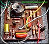
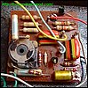
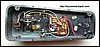
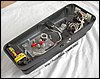
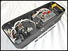
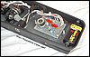
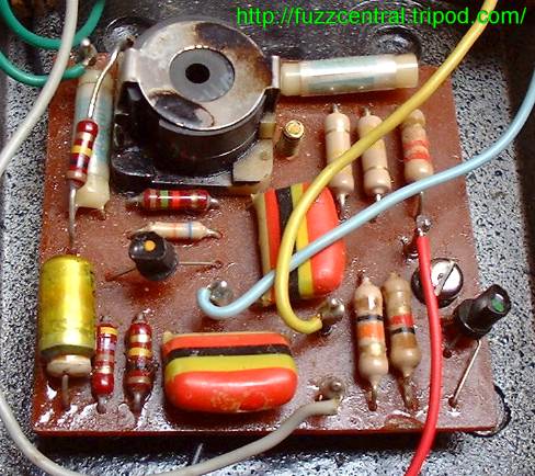
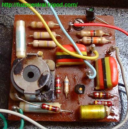
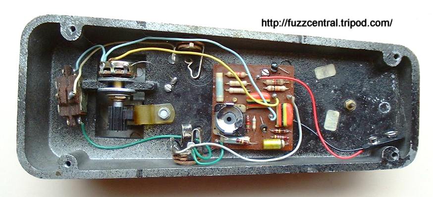
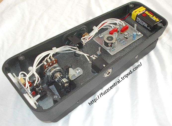
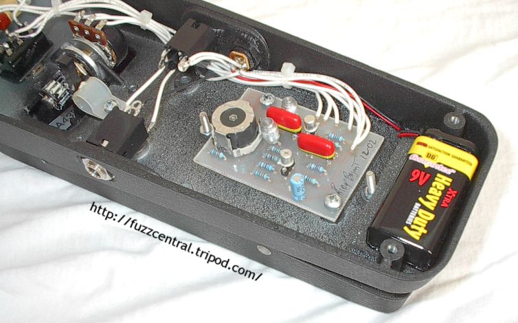
Below are some pictures of an original Vox Clyde McCoy wah pedal. In the pictures you can see the
100K resistor paralleling the inductor (one end of the resistor is soldered directly to one of the inductor's posts),
the tropical fish capacitors, and the "small hole" Halo inductor. Also take a look at this Clyde's switch in the third
picture. That's an Arrow DPDT, but notice how it's wired...as a SPDT. What gives guys? Special thanks to Stuart Castledine
for providing me with these very nice pictures!
|
|
|
|
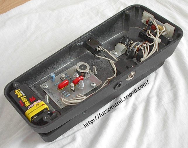
Pictures of my Clyde McCoy Clone, complete with JFET output buffer mounted at the "toe" of the case (pictures updated 4/4/2004):
|
|
|
|
A common problem is that the wah pedal simply won't wah when put in series before a fuzz pedal.
Unfortunately, this is the way it sounds the best to most people. This problem can be solved by adding an output
buffer to your new McCoy clone, which won't alter the tone of the pedal. This is a simple JFET buffer that's based
on the Wah Wah project at Tonepad, and can be added to any wah pedal that doesn't have an output buffer, namely the
Vox V847s and the Dunlop Crybabys. The input impedance of this buffer is set by the 1M resistor from the Gate of the
JFET to ground. Since this buffer can give a slight volume boost, a 100K trimpot is on the output of the buffer to
act as a volume pot so you can keep the volume of the wah pedal at the same level as when it's off. Below is a
schematic of the Clyde McCoy wah with the output buffer highlighted in red:
|
Note: These files are NOT to be used in a pedal that you are building for profit. The PCB file is
copyrighted artwork and is subject to a licensing fee.
Vox Clyde McCoy PCB
|
Here
|
Vox Clyde McCoy Layout
|
Here
|
Vox Clyde McCoy Parts List
|
Here
|
Build Difficulty: Moderate
|

|
Output Buffer PCB
|
Here
|
Output Buffer Layout
|
Here
|
Outut Buffer Parts List
|
Here
|
Build Difficulty: Easy
|

|
|
With the PCB and layout files you can build several different wah pedals, but as you can probably
tell from the labelling on the transfer pattern, I originally intended it for the McCoy circuit. The layout will accept
Stuart Castledine's Halo replica inductor, which has a lead spacing of 0.4" all the way around, and it will also accept
the original inductors from Crybabys and V847s, which have a lead spacing of 0.3" all the way around. The PCB and Layout for the
output buffer can be mounted just about anywhere in the wah shell. I usually stick it on the vertical wall at the
front of the wah pedal in front of the bypass switch.
|
|
|
| |
|
|
|
