Effects FAQs
|
|
|
I've received a lot of emails asking how I apply the finish to me pedals, so here's a brief "lesson"
of my painting technique. The way I finish the boxes is pretty simple. First I sand the entire box with an orbital
sander with a piece of 220-grit sandpaper attached. I just sand the sides smooth, but I spend extra time on the top
of the box and the rear cover to sand in neat looking swirls, which adds a lot of depth to the metal. To add the swirls, I tip
the orbital sander over to 45 degrees or so, so that just the edge of the paper is contacting the aluminum, and I move the sander
over the top of the pedal in different patterns to make the swirls random (and more interesting). Then I wash the
pedal with water and Comet cleaner to remove the sanding dust and dry the pedal off with a paper towel and a few good
blasts from compressed air. Once it's dry I drill the box using RG Keen's Hammond 1590BB paper template.
Once the box is drilled I carefully mask off the top of the box with some masking tape, then start spraying the sides of
the pedal with whatever colors I've decided to use and the pattern that I've chosen. All the paint that I use, including the clear paint, is
lacquer--which dries faster and harder than enamel without having to be baked on. After the painting is done I use the
laser printer decal sheets that I buy from Steve Daniels to apply the decals. Once they've dried I give the pedal 2 more
coats of clear lacquer to finish it off and give it a nice shine.
|
|
|
Here are some diagrams of how the stomp switches are wired up for true bypass. I've included three
diagrams...the 3PDT with LED indicator for NPN, 3PDT with LED indicator for PNP, and DPDT with no LED indicator.
|
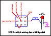
NPN 3PDT Wiring
|
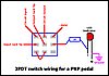
PNP 3PDT Wiring
|
NPN & PNP DPDT Wiring
|
|
|
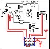
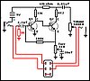
Below are a couple of examples of how the schematics on the site would look if the stomp switch
were drawn into them, in this case the 3PDT with a LED indicator, and a DPDT with no LED indicator. I've provided
examples for the NPN and PNP versions of the Fuzz Face, but the examples would be correct for all the other
schematics too. The DPDT switch can be wired the same way for NPN or PNP.
|

NPN Complete Circuit 3PDT Wiring
|
PNP Complete Circuit 3PDT Wiring
|
Complete Circuit DPDT Wiring
|
|
|
Here's a little diagram that shows how to wire the power switching setup on a pedal using a stereo input
jack, a 9V battery clip, and a power adapter jack with an internal switch (like the one listed on all of my pedal parts lists).
Make a note that this diagram is for negative ground pedals, and WILL NOT work for positive ground PNP pedals. The
polarity of the power adapter jack tip is positive outside, negative center.
|
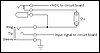
Input Jack, Battery, and Adapter jack wiring.
|
|
|
Below is a diagram that shows how to correctly wire the DC power jack that I use on my pedals (see
the project parts lists for the Mouser part number...). This wiring diagram will only work for NPN negative ground pedals.
It will NOT work for PNP positive ground pedals.
|
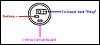
Power Jack Wiring.
|
|
|
For the PCB and Layouts that I've drawn, scale them down to 30% of their original size in order
to print them out properly for ironing on to copper PC boards. For the layouts that Bill Lawrence has contributed, there
are measurements on each of his layouts that tell you the height and width of the board in inches. This will ensure that
the PCB pattern is at its correct size and ready to transfer.
|
|
|
For the transistor sockets that I use in my pedals, buy the SIP sockets from Mouser. The ones that I buy
come in strips of 64 indiviudal pins and they can be broken into any length that you need. The Mouser part number is 575-193164
and they cost $1.87 per strip. You can also use them as resistor and capacitor sockets too!
|
|
|
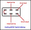
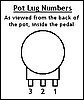
Here's how I number the solder lugs of the pots. The image would be if you were looking at the back of
the pot from inside the pedal. Click the thumbnail for a larger version:
|
|
|
|
Unfortunately, I do not make circuit boards for the projects on this site to sell.
|
|
|
I personally do not think that wiring up PNP transistors (Silicon or Germanium) as negative ground is
one of the best ideas. The PNP transistors are simply not meant to function with a negative ground and osciallation and
"motorboating" sounds are common results of wiring a Fuzz Face with PNP transistors as such. Here's some more information
from R.G. Keen:
While in theory, the negative ground conversion for FF and other PNP circuits ought to work every time, there are a
significant number of times where it causes oscillation, motorboating, etc. Sometimes you can clean this up by putting a big
freaking capacitor across the power leads, sometimes you also need a low-impedance 0.1µF ceramic, too, and sometimes you need
divine intervention. Try it if you want, but be aware that there are conditions and layouts that will not be trouble free if
you flip power and ground
So, in my opinion, I would always leave PNP transistor-equipped circuits as positive ground. A circuit like the Fuzz Face will
use such a small amount of current that a battery will last a very long time, even with heavy use...as long as there's not an LED
to increase current draw. If you're absolutely determined to use a negative ground Fuzz Face, I would suggest that you go through
the extra trouble of getting some NPN Germanium transistors which will work properly with a positive power supply and negative ground.
Small Bear Electronics has NPN Germanium transistors.
|
|
|
In order to get a fuzz pedal, meant for regular 6-string electric guitar, to work with a bass guitar, you'll need
to experiment with larger value input and output capacitors until you get the desired bass response. There's no set value that will
always provide just the right amount of bass, so I would recommend using sockets to try different values.
|