|
|
| |
|
|
| |
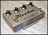
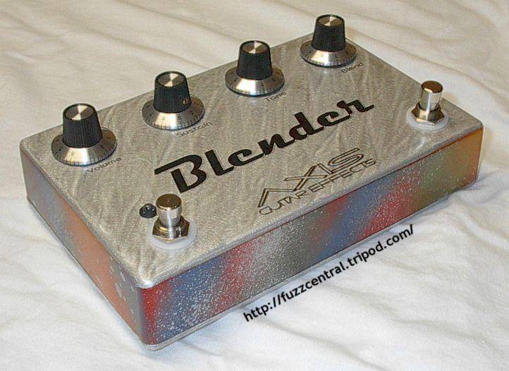
Fender Blender
All I can really say about this pedal is WOW! This thing can get really loud...so loud that it
rattles the windows and makes the floors vibrate. (I'm not kidding!) This pedal has a very "spongy" or "rubbery"
sound to it...that's really the best way that I can think of to describe it. I think the overall sound of this beast
is due to the four Germanium diodes that it requires. For the five transistors I used 2N5089, which are high enough
gain to satisfy this circuit. If you're wondering, I didn't gain check those transistors before I soldered them in,
I just randomly grabbed them from the little bag one at a time. I also used all linear taper pots because all my
audio tapers are tied up with other projects ;) This pedal isn't for the faint of heart because it takes a while to
solder everything together and also because once you get it all put together it's WILD! This pedal will set you back
more cash than other octave/fuzz pedals like the Tyco Octavia and the Ampeg Scrambler because it uses so many
components, because it uses two footswitches, and because it requires a larger enclosure. But overall this is a VERY
unique pedal...one that everyone should experience at least once in their lives!
Before you email: NO...I do not build the Fender Blender to sell. This pedal is too
complicated to build on a regular basis, so it's just not cost effective. If you'd like a custom built Octave/Fuzz
pedal, I would recommend my Axis Skrambler. It's a
much better sounding pedal and it's been wildly popular! Below is a schematic of the Fender Blender:
|
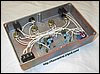
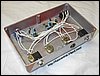
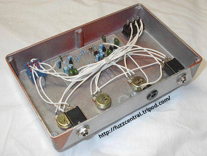
Below are some pictures of my Fender Blender clone, built in the Hammond 1590D box. Click the thumbnail
for the full-sized image. Use your browser's "Back" button to return to this page.
|
|
|
|
Note: These files are NOT to be used in a pedal that you are building for profit. The PCB file is
copyrighted artwork and is subject to a licensing fee.
Fender Blender PCB
|
Here
|
Fender Blender Layout
|
Here
|
Fender Blender Parts List
|
Here
|
Build Difficulty: Difficult
|

|
|
This PCB and Layout was drawn by Bill Lawrence, so thanks to him for this layout! You'll
notice that the 0.1µF capacitor that goes from the wiper arm of the "Blend" pot to the tip of the output jack isn't
included on the layout. This capacitor should be mounted directly to the "Blend" pot.
|
|
|
| |
|
|
|

