|
|
| |
|
|
| |
Vox ToneBender
The Vox ToneBender was another pedal in the ToneBender series, but it differs from most because of
it's greatly increased treble response and two transistor circuit. The circuit itself predates the Fuzz Face, which means that the
famous Arbiter Electronics Fuzz Face was probably based on this circuit. Take a look at the schematic of the Vox ToneBender
down the page and you'll notice some big differences between the two circuits right away. For one, the input and output capacitors
in the Vox ToneBender are MUCH smaller in value than the input and output capacitors in the Fuzz Face. The Vox ToneBender will have
a lot more treble response than the Fuzz Face...maybe to help brighten up those characteristically "dark" sounding British amps some.
Using a Vox ToneBender with a Fender Twin, or any other Fender amp, would be nearly ear-piercing with all the treble that'd be blasting
through. Another change that will remove more bass is the bypass capacitor on the wiper of the "attack" pot. Using a 15µF instead of a
22µF will reduce bass and it will also back off the fuzz some, too. The 50K "level" pot will also pass more treble compared to the 500K
pots used in the Fuzz Face. Another thing makes a noticeable difference is the 1K resistor between the collector resistors of the two transistors.
In the Fuzz Face this resistor is 470 ohms in the Germanium versions and 330 ohms in the Silicon versions. Using a 1K resistor will give more
output from the circuit, which really helps. Why didn't Arbiter use this trick in the Fuzz Face? Who knows... If you're looking for a great
little fuzz pedal that has plenty of treble bite, then the Vox ToneBender will certainly be the ticket towards a brighter...erm...future ;)
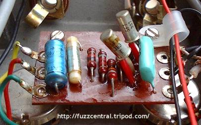
Below is a picture of the circuit board in a Vox ToneBender with SFT337 and SFT363E transistors. I've also seen a Vox ToneBender circuit
board with a SFT337 for Q1 and an OC76 for Q2.
Below is a schematic of the Vox ToneBender:
Many people believe that the legendary and very rare ToneBender MKI is nearly identical to the Vox ToneBender...you know the one...the
gold-painted folded steel enclosure one. The only said difference between the two circuits are the transistors. The Vox ToneBender uses a SFT337
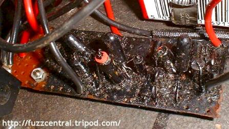
for Q1 and a SFT363E for Q2, while the ToneBender MKI is said to have used OC76 transistors for Q1 and Q2. I have personally seen the inside
of a ToneBender MKI, and even though the circuit board was covered in black goop...there were clearly three transistors on the circuit board.
Perhaps the early ToneBender MKIs came with the two-transistor circuit, and then later it was switched to a different three-transistor circuit.
Maybe one day (soon I hope) someone will get ahold of a MKI and reverse engineer it so the mystery will be put to rest. Here's a picture of a
ToneBender MKI circuit board with three clearly visible transistors:
|
Note: These files are NOT to be used in a pedal that you are building for profit. The PCB file is
copyrighted artwork and is subject to a licensing fee.
Vox ToneBender PCB
|
Here
|
Vox ToneBender Layout
|
Here
|
Vox ToneBender Parts List
|
Here
|
Build Difficulty: Easy
|

|
|
Above the is the PCB, Layout and parts list that can be used to build the Vox ToneBender. I have replaced
the 8K2 resistor on the collector of Q2 with a 20K trimpot so that you can adjust the voltage on Q2's collector to -4.5VDC, which
will give the best overall sound. A 1M input pulldown resistor has been added to the circuit board so that you can use true bypass
switching without the "pop" caused by a leaky input capacitor. I've also added a 47µF capacitor to the circuit for power supply
filtering. This capacitor is optional, but recommended because it will help remove additional hum and hiss. The trimpot mod is not
shown on the schematic above, but the input pulldown resistor and power supply filtering capacitor are highlighted in blue.
|
|
|
| |
|
|
|
